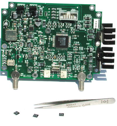
Four ICs pack tremendous power and flexibility into a 4" Hammond 1590-series chassis. Controlled by the PC parallel port, this hybrid DDS/PLL synthesizer delivers full-octave coverage between 1000 and 2000 MHz with sub-1 Hz resolution and commercial-quality phase-noise performance.
Icom IC-R7000 first LO synthesizer: -51.5 dBc/Hz at 250
Hz
KE5FX hybrid synthesizer: -80.3 dBc/Hz at 250
Hz
Icom IC-R7000 first LO synthesizer: -70.5 dBc/Hz at 1
kHz
KE5FX hybrid synthesizer: -83.7 dBc/Hz at 1
kHz
Icom IC-R7000 first LO synthesizer: -99.9 dBc/Hz at 10
kHz
KE5FX hybrid synthesizer: -91.9 dBc/Hz at 10
kHz
1500 Hz loop bandwidth: -81.5 dBc/Hz at 250
Hz
2500 Hz loop bandwidth: -80.3 dBc/Hz at 250
Hz
3500 Hz loop bandwidth: -82.3 dBc/Hz at 250
Hz
1500 Hz loop bandwidth: -79.3 dBc/Hz at 1
kHz
2500 Hz loop bandwidth: -83.7 dBc/Hz at 1
kHz
3500 Hz loop bandwidth: -84.9 dBc/Hz at 1
kHz
1500 Hz loop bandwidth: -93.9 dBc/Hz at 10
kHz
2500 Hz loop bandwidth: -91.9 dBc/Hz at 10
kHz
3500 Hz loop bandwidth: -87.9 dBc/Hz at 10
kHz
Icom IC-R7000 first LO synthesizer VCO tuning line, 770 MHz
to 1030 MHz
Icom IC-R7000 first LO synthesizer VCO
tuning line, 1030 MHz to 770 MHz
KE5FX hybrid
synthesizer VCO tuning line, 1000 MHz to 2000 MHz
KE5FX hybrid synthesizer VCO tuning line, 2000 MHz to 1000
MHz
Improved spur performance (see spur-search results below) is obtained with an inexpensive monolithic crystal filter following the AD9854 DDS. This graph shows the DDS coverage range overlapped with the crystal filter's close-in response in an early prototype.
| IDC Connector | LPT Port | AVR Port 'A' Signal |
|---|---|---|
| 1 | 15 | PA0 |
| 2 | 9 | PA1 |
| 3 | - | - |
| 4 | 6 | PA2 |
| 5 | 7 | PA3 |
| 6 | 8 | PA4 |
| 7 | 4 | PA5 |
| 8 | 2 | PA6 |
| 9 | 3 | PA7 |
| 10 | 18-25 | GND |
Complete parts list including Digi-Key, Mini-Circuits, and Analog Devices part numbers
Note:
Component values in list supercede those in schematics above
R101: 1.3K ohms (P1.3KECT-ND)
R102,
103: 100 ohms (P100ECT-ND)
(50-ohm external clock input only)
R102, 103: 1K ohms (P1.0KECT-ND)
(Internal clock source only)
R403: 1K ohms (P1.0KECT-ND)
R104:
3.9K ohms (P3.9KECT-ND)
R105-108,
212: 51 ohms (P51ECT-ND)
R201-203:
18 ohms (P18ECT-ND)
R206,
207, 510-514: 10K ohms (P10KECT-ND)
R210,
211, 218: 22 ohms (P22ECT-ND)
R213-216:
470 ohms (P470ECT-ND)
R217:
4.7K ohms (P4.7KECT-ND)
(ADF4112 PLL chip only; omit for LMX2326)
R301, 303: 4.7K ohms (P4.7KECT-ND)
R401,
402, 501, 507-509, 109-112: 100 ohms (P100ECT-ND)
R502-506:
3.3K ohms (P3.3KECT-ND)
C101, 103, 207, 208, 209, 401: 0.01 uF/50V ceramic (399-1234-1-ND)
C102,
104, 106, 202, 204, 205, 211, 215, 219, 224, 226, 309, 311, 312, 315, 317, 318,
407, 408: 0.1 uF/50V ceramic (PCC104BCT-ND)
C201,
203, 206, 210, 217, 220: 100 pF/50V ceramic (399-1205-1-ND)
C214,
321: 47 uF/35V electrolytic (PCE3280CT-ND)
C218,
228, 302, 304, 307, 308, 313, 314, 409: 10 uF/16V tantalum (399-1595-1-ND)
C221-223,
225, 406: 0.001 uF/50V ceramic (PCC102BCT-ND)
C301,
319, 320, 322: 10 uF/35V electrolytic (PCE3413CT-ND)
C403,
405: 270 pF/50V NPO ceramic (399-1209-1-ND)
C404:
470 pF/50V NPO ceramic (399-1213-1-ND)
D301-303: 1N4002 (DL4002DICT-ND)
D304:
5.6V 500 mW Zener (BZT52C5V6-7DICT-ND)
D306:
5.6V 500 mW Zener (5V VCOs only) (BZT52C5V6-7DICT-ND)
D306:
12V 500 mW Zener (12V VCOs only) (BZT52C12-7DICT-ND)
F401: ECS-10.7-15B monolithic crystal filter, +/- 7.5 kHz bandwidth, 25 kHz
stopband (X704-ND)
J101, 201: SMA female bulkhead jack (J569-ND)
J301:
4-position straight header (A1912-ND)
J501:
10-position shrouded header (MHB10K-ND)
L402,403: 0.91 uH RF choke (DN1015CT-ND)
L201,
202, 204-207, 301, 404: 33 uH 115 mA RF choke (TKS2638CT-ND)
L203:
Mini-Circuits ADCH-80A
Q301, 303: 2SC1847 (2SC18470Q-ND)
T401, 402: Mini-Circuits T36-1-KK81
36:1 RF transformer
U101: Analog Devices AD9852AST
DDS synthesizer
U102: Clock module for internal-clock option (ECS-3953M)
U201:
Analog Devices ADF4112BRU
3.0 GHz RF PLL frequency synthesizer
U201: National Semiconductor LMX2326TM 2.8 GHz RF PLL
frequency synthesizer (LMX2326TM-ND)
U202:
Burr-Brown OPA27 low-noise operational amplifier (OPA27GU-ND)
U203:
Mini-Circuits ROS-2150VW
1-2 GHz VCO
U204: Mini-Circuits GALI-5
monolithic amplifier
U301, 302: Linear Technology LT1086-3.3 voltage
regulator (LT1086CT-3.3-ND)
U304:
7812 voltage regulator (NJM7812FA-ND)
U401:
Linear Technology LT1016 precision comparator (LT1016CS8-ND)
Miscellaneous hardware and optional parts
Hammond 1590BB aluminum enclosure (HM152-ND)
TO-220
mounting kits for U301, U302 (4724K-ND)
10-position
IDC socket for J501 (MKC10A-ND)
10-position
ribbon cable (MC10G-5-ND
Loop filter components (ROS-2150VW VCO, 2.5 kHz loop bandwidth):
R208: 150 ohms (P150ECT-ND)
R209:
82 ohms (P82ECT-ND)
C212:
1 uF/35V tantalum (PCS6105CT-ND)
C213:
0.1 uF/50V ceramic (PCC104BCT-ND)
C216:
0.1 uF/50V ceramic (PCC104BCT-ND)
AutoTrax .PCB file (by Richard Hosking) -- tested and working with components above
Microsoft Works spreadsheet for loop-filter design (by Richard Hosking)
Miscellaneous Atmel assembly routines for AD9852 and related components (by Richard Hosking)
Random spur search
results for 25 kHz crystal filter following DDS, 10 MHz clock with adaptive
multiplier (8-12X) algorithm, 5000 samples (20MB)
No significant spurs
at any of 5,000 randomly-selected frequencies
Unzip each of the above files into separate, empty directories and run HPGLVIEW.EXE to browse spectrum-analyzer plots -- or download the current version of the HP-GL/2 tools (highly recommended!)
Cross-platform Atmel/Win32 C++ control software, with source (New as of 19-Oct-02!)
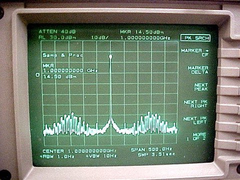
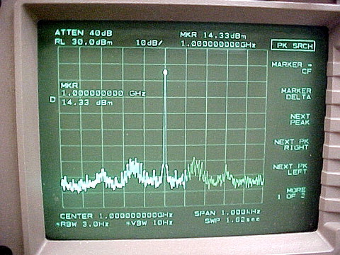
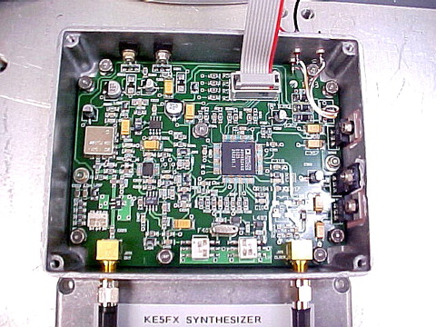
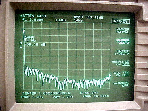
November 3, 2003 - Miguel Llanes of Rockwell-Collins sends along a
few shots of his synthesizer PCB and its performance as characterized on an HP
8563E spectrum analyzer. This FFT-based instrument delivers better close-in
measurement performance than the Tektronix 494AP used to capture the screenshots
at the top of the page.
Miguel was also kind enough to point out some notation errors on the schematics. As the parts list indicates, C214 and C321 should both be 47 uF/35V parts, while C313 should be 10 uF/16V. In the previous schematic drafts, all three capacitors were marked as 22 uF. (It's important not to use too large a capacitor at C313, as I've seen U201 malfunction with slow power-supply risetimes at the junction of pins 10 and 15. -- jm)
One correction to the parts list was also necessary: the Digi-Key part number for C101, 103, 207, 208, 209, and 401 has changed from PCC103BCT-ND to 399-1234-1-ND. The former part number no longer appears to be stocked.
All of these corrections have been made to the page contents above. Many thanks to Miguel, KG4LXC for the feedback!