Solar & multi-purpose RF-Spectrometer
by Franz Knüttel, DC9FF & Eckhard Kantz, DL9GMU
Contact:
f.knuettel@worldonline.de /
kantz@wegalink.de
The early versions of the hard- and software described here were developed during the years 2000/2001. Preliminary articles were published in ERAC-newsletter No. 21/Nov.2001 and a follow up article and test report was published by Mr. Josef Hausmann in Newsletter 23/Oct.2002.
A much more sophisticated version of a solar spectrometer in professional quality + a wealth of additional information was published in an article in NL22 and 23 by Mr. Ernst Lankeit. Especially the preamp circuits and the description of usable antenna systems should be of interest, as these parts are not subject of this article.
Block Diagram:
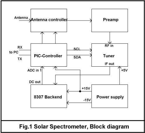
A block diagram of the Spectrometer is shown in Fig. 1. The hardware consists of 3 main building blocks, each one should be built into a separate tin box:
- The PIC-Controller is connected to a PC with the spectrometer software running
- The Cable Tuner (PHILIPS CD1316L) converting the bands from ca. 50Mhz to 850Mhz to an IF of 36Mhz
- The Backend with 2. mixer down to 10.7 Mhz, 2 ceramic band filters providing a 180Khz broad IF-channel and the log-detector AD8307, converting the RF-power at it's input to a dB-linear (logarithmic) output voltage.
A Narrow-band version for spectral line work with a linear detector, based on the scanning spectrometer of the Haystack Observatory, published in Sky & Telescope 8/96 is shown in Fig. 3.
Short functional description:
The spectrometer-functions are controlled by the spectrometer-software, written by Eckhard Kantz. The latest version can be downloaded from:
Multi Purpose Radio Frequency Spectrometer
The software controls the scanning of the RF-range via the RS232-interface by sending commands to the PIC-Controller.
The PIC-controller "translates" the ASCII-commands sent by the PC into the I2C-code of the cable tuner, measures and returns the power level from the log-converter.
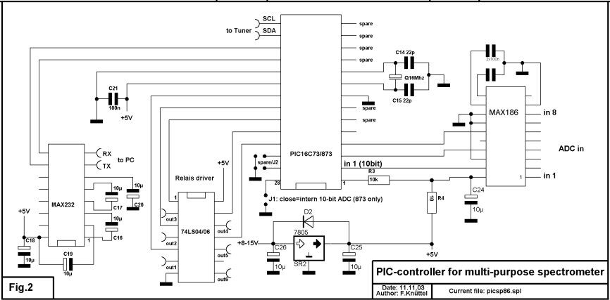
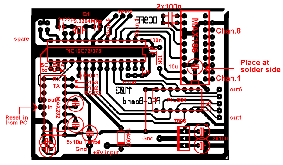
The PIC-Controller:
The schematics of the PIC-Controller are shown in Fig.2. The RS232-interface uses a standard MAX232-driver. The cable tuner is controlled via lines SDA (serial data) and SCL (serial clock).
Five additional PIC outputs can be set or cleared under software control and can be used to select different antennas, or to switch attenuators etc. into the RF-path using relays suitable for RF-applications.
The latest version of the PIC-software uses an inexpensive flash-Eeprom type PIC16C873, which is pinout-compatible with the PIC16C73 used in the early version.
Costs can be reduced further by enabling the internal 10-bit ADC of the 873 instead of using a MAX186, simply by grounding RB7 (pin 28, J1 in Fig.3) and connecting the output of the 8307-backend to RA0 (pin 2).
You can download the PIC-software as .zip-file from here
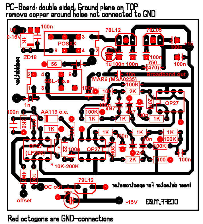
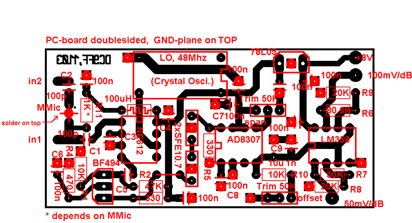
The 8307 Backend:
The output of the Tuner is mixed with a 48Mhz-Oszillator to obtain a 10.7Mhz mixing product. Two ceramic filters limit the signal bandwidth to about 180kHz.
An AD8307-log-detector converts the signal to DC, 2 OP-amps buffer and amplify the signal. The outputs of one of the OP's is connected to one of the ADC inputs. Each output may be connected to it's own ADC-input (we have 8), to obtain a crude amplification control by the software.
Note that the exact IF-frequency is 48-10.7=37.3 Mhz, not 36 Mhz. This deviation should be considered when calculating the actual input frequency.
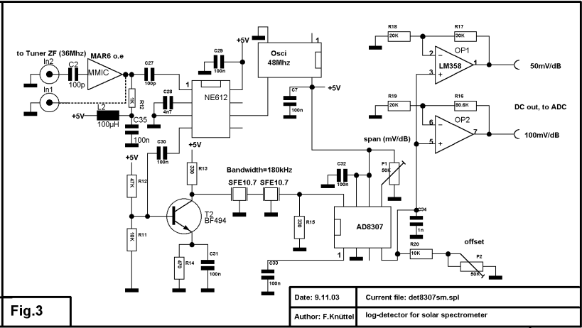
The Linear Detector:
Spectral line work at the hydrogen line or strong maser lines is obviously one of the most interesting areas in amateur radio astronomy and surely deserves more interest in the future.
Examples of very interesting pioneer work in the USA can be found under:
www.jupiterspacestation.org/Meth122FirstLight.html
In contrast to a full power radio telescope which is designed as a wide band receiver on a single frequency, a radio telescope specialized for spectral line work has to divide a wider range (several Mhz) into a set of single consecutive frequencies (the spectrum), each with a smaller bandwidth.
Plans and layouts of several versions of linear detectors are included in the .zip-file downloadable from: here
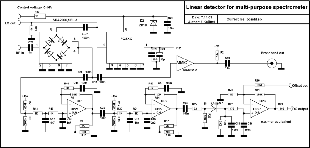
The linear detectors use a simple technique called direct conversion with an intermediate frequency (IF) of 0 Hz. The filtering is done by simple active RC-filters yielding a bandwidth of 32 kHz.
Due to the reception of both sidebands mirrored around 0 Hz (DSB=Double SideBand-signal), the resulting bandwidth is appr. 2x32 kHz, fitting nicely to the minimum step width of the cable tuner of 62.5 kHz.
A DSB-version with a bandwidth of 1.5Mhz, matching the conversion speed of the Fast Sampler from workshop.eracnet.org/sampler/sampler.htm will be published soon.
Applications:
No spectral line of interest falls into the frequency range of the cable tuner itself. The next accessible line is the line of neutral hydrogen at 1420 Mhz.
Modern SAT-Tuners in general cover a range from 900 to 2150 Mhz. The commonly used SAT-IF is 479 Mhz, accessible with the cable tuner
So, with a SAT-tuner set to 1420Mhz +/- Doppler, the down converted H-line appears at 479 Mhz and can be scanned by the cable tuner, provided, you are able to tap on the 479 Mhz IF of the tuner. Older models, around 1990-1993) are better suited for that purpose than "modern" ones with a higher degree of integration.
If you are lucky, you can get hold of a version with the IF available at an output pin of the downconverter (this is the tin box inside the housing of the tuner with the F-plug attached).
Later models with higher integration usually keep the IF inside the converter, which has to be opened and the IF tapped on (a job for those with a fine soldering iron and good eyesight!)
If you tap on the IF before it enters the surface wave filter at the output, you get a very strong broadband output over several 100 Mhz.
Plans and layouts can be downloaded here
PIC board
Logarithmic detector board
Linear detector board